Table Of Content
With both Kafka and Kora, Confluent provides a platform that is more elastic, reliable, and performant than other streaming platforms. Detecting errors and anomalies in data flow, as well as implementing effective error-handling mechanisms, is essential. This becomes challenging in large and intricate data flow scenarios where pinpointing the root cause of an issue can be time-consuming. As data moves between different processing points, ensuring its security and maintaining user privacy become significant challenges.
Add data flows
It still describes the whole system but with emphasis on its main function and more sub-processes for easy digestion. A DFD can be divided into levels and layers, starting with level 0; thus, users can focus on describing a particular stage. An external entity, also known as terminators, sources, sinks, or actors, is an outside process where information enters or leaves the system. Click it and drag it to where you want to add a title to the diagram. Type the title, and if you’d like to, adjust the font and type size using the shortcut keys at the top of the screen.
Examples of data flow diagrams
However, a Physical DFD shows how the system is actually implemented now, or how it will be. For example, in a Logical DFD, the processes would be business activities, while in a Physical DFD, the processes would be programs and manual procedures. Three other experts contributing to this rise in DFD methodology were Tom DeMarco, Chris Gane and Trish Sarson.

Understanding Data-Defined Software
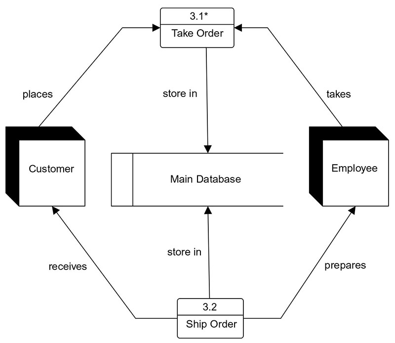
A process can be decomposed to a finer level of details, for representing how data is being processed within the process. Invite them to join you on the board or download your data flow diagram as an image or PDF. Click on the shapes to edit colors, fonts, and any other graphic elements of your data flow diagram. Processes in diagram 0 (with a whole number) can be exploded further to represent details of the processing activities. Example below shows the next level ((Diagram 1) of process explosion. Unlike other flowchart symbols, which are triangles, rectangles, or circles, a DFD uses stick-figure drawings to demonstrate external entities.
Cardio Flow obtains FDA approval for blood flow analysis software - Medical Device Network
Cardio Flow obtains FDA approval for blood flow analysis software.
Posted: Tue, 20 Jun 2023 07:00:00 GMT [source]
Visualize marketing campaigns and client and prospect info to take action, and track tasks and status updates for the team. Make sure you use our diagramming shapes library to represent each component with the right shape. Cisco offers data center and access networking solutions built for scale with industry-leading automation, programmability, and real-time visibility. Before getting to the steps, let’s go through some rules on making one first.
Start at Level 0
In an age where data reigns, data-defined software development emerges as the future of application creation. It untethers development from the confines of code, streamlining processes, fostering innovation and enhancing adaptability. DDS promises a world where software creation becomes more intuitive, collaborative and responsive to ever-changing business needs.
A natural language interface for automatic generation of data flow diagram using web extraction techniques - ScienceDirect.com
A natural language interface for automatic generation of data flow diagram using web extraction techniques.
Posted: Wed, 11 Jan 2023 21:33:07 GMT [source]
It can be used to streamline the everyday systems and workflow of a business. Data flow diagrams are split into two categories based on the flow that needs to be visualized. A data flow diagram can either be a logical data flow diagram or a physical data flow diagram.
Possible outputs include user alerts about upcoming due dates or notifications about new library members. Repeat the previous step and go deeper each time you want to hone in on a specific system or process. But remember that you want the data flow diagram to be easily understandable.
How to create a new canvas app using Copilot
A process can perform several functions, from carrying out computations, categorizing information based on logic, or using business rules to change the flow. Click the highlighted text in the box and type the name of the external entity. For our example, we’re typing “customer.” You can use the curved arrow in the top left corner of the square to rotate the symbol. Delete a symbol by clicking it and pressing delete on your keyboard. In the left column of the screen, you’ll notice a lot of shapes and symbols.
However, diving in too deep into the small details can complicate the tool, hindering communications and efficiency. It is labeled with a short and simple term that describes the whole process, such as “Submit payment”. External entities can either be a person, an organization, or a computer system. This guide is brought to you by Zen Flowchart, the simplest flowchart maker. Check out this guide to physical and logical DFDs for more information. Before diving into more complex DFDs, check the work you’ve already done to make sure it’s accurate and complete.
Proper data flow design is key in optimizing data processing efficiency, reducing bottlenecks, and ensuring the reliable delivery of information within complex computing environments. Data-flow diagrams can be regarded as inverted Petri nets, because places in such networks correspond to the semantics of data memories. Analogously, the semantics of transitions from Petri nets and data flows and functions from data-flow diagrams should be considered equivalent. But what does a data flow diagram look like in practice — and how does it help your business? The most common and intuitive DFDs are level 0 DFDs, also called context diagrams. They’re digestible, high-level overviews of the flow of information through a system or process, so almost anyone can understand it.
The diagramming software tools like the above ones provide pre-ready templates that save your time and efforts. Here is our level 1 data flow example – a decomposition of the Clothes Ordering System illustrated in the context DFD. As you saw above context DFD contains only one process and does not illustrate any data store. Drive alignment with your team by collaborating in the same space.
Use our DFD examples and specialized notations to visually represent the flow of data through your system. Get started with a template, and then use our shapes to customize your processes, data stores, data flows and external entities. Now let’s cover how these diagrams fit into the Unified Modeling Language (UML) world. UML diagrams and data flow diagrams appear similar, but there are some key differences.UML is a modeling language used in object-oriented software development. For example, software developers use UML to offer a more detailed overview of a process and explain how software engineering is done. There are 14 official types of UML diagrams.On the other hand, data flow diagrams show how data flows through a system.


No comments:
Post a Comment